Raspberry Pi LED Illumination and Imaging Station
Meter-Made: Raspberry Pi LED Illumination and Imaging Station Tutorial
by Allison Tielking (Winter 2014 MICDS Highschool Intern), Tom Liu (2014 Summer STARS student) and Dmitri Nusinow
- [Setting up Raspberry Pi](#setup)
- [Setting up Raspberry Pi Camera](#cam)
- [Option: Enable camera](#op-cam)
- [Option: Change camera focus](#op-focus)
- [Option: Cutoff Filters](#op-filters)
- [Option: Disable camera LED](#op-led) </ul>
- [Setting up LED array](#led-array)
- [Using a MOSFET Transistor to Control Array](#MOSFET)
- [Installing GPIO](#install_GPIO)
- [Coordinating imaging and turning on LED lights through GPIO](#camera.sh)
- [Time-Lapse Imaging](#time-lapse)
- [Setting up imaging station](#station)
- [Plant Seed Sterilization](#liquid)
- [Measuring Plant Hypocotyl Length](#hypocotyl) </ol> Setting up Raspberry Pi. [back to top](#contents)
1. Open the Raspberry Pi Complete Starter Kit and take out its contents.
2. Insert the Noobs Preloaded SD Card 8Gb, Ethernet cable, USB mouse, USB keyboard and a HDMI Cable into the right ports.
3. Connect the HDMI Cable into the monitor (you may need a HDMI to VGA/DVI adapter depending on the monitor.)
4. Internet connection is not required, however, if you want internet, plug in an Ethernet cable to the Raspberry Pi.
5. Plug in the Micro USB Power Supply, Pi will start automatically.
6. If this is the first time you are using the Pi, then load Raspbian OS.
7. The after it is finished, click OK. The Pi will reboot (if not, reboot the Pi (unplug and replug in) and take you to the Raspberry Pi Software Configuration tool (raspi-config).
8. Setup Options to change: enable camera, change password, set to local timezone.
9. The default username and password is pi and raspberry.
Note: Do not be alarmed when no writing appears when you are typing in the password, this is just a security feature of Linux. However, to change the password, type in the command: </p> ```python sudo raspi-config ```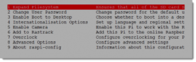
10. After you have successfully logged in, the command line prompt should read:
```python pi@raspberrypi~$ ```Setting the Time and Date on your Raspberry Pi. [back to top](#contents)
Note: The Rasberry Pi does not have a very accurate clock, so the time needs to be reset and coordinated frequently to avoid drift. To set the date:
1. Type the following:
```python #sudo date -s Day Of Week Month Day Hours:Minutes:Seconds Timezone Year #for example if it is 07/11/2014 at 11:59:30 on Friday in the Central timezone: sudo date -s Fri Jul 11 11:59:30 CDT 2014 ```2. This will update the time. If the Raspberry Pi reboots, check the time and date using the command:
```python date ```Setting up the Raspberry Pi camera. [back to top](#contents) We followed instructions that can be found [here](http://thepihut.com/pages/how-to-install-the-raspberry-pi-camera)
1. Open up your Raspberry Pi Camera module. Be aware that the camera can be damaged by static electricity. Before removing the camera from its grey anti-static bag, make sure you have discharged yourself by touching a grounded object (e.g. a radiator or PC Chassis).
2. Install the Raspberry Pi Camera module by inserting the cable into the Raspberry Pi. The cable slots into the connector situated between the Ethernet and HDMI ports, with the silver connectors facing the HDMI port.1
3. Boot up your Raspberry Pi.
4. To take a photo, enter the command:
```python raspistill -o image.jpg ```5. The picture is now in your home folder, "labeled image.jpg"
Optional: If you did not enable the camera option after installing the OS and running raspi-config for the first time. [back to top](#contents)1. From the prompt, run: ```python sudo raspi-config #If the "camera" option is not listed, you will need to update your Raspberry Pi: sudo apt-get update sudo apt-get upgrade ```
2. From the prompt, run:
```python sudo raspi-config #you should now see the "camera" option. ```3. Navigate to the camera option, and enable it. Select Finish and reboot your Raspberry Pi.
Optional: Changing focus of the camera. [back to top](#contents)See video from George Wang:
1. The Raspberry Pi camera's focus is initially set to infinite, if you want a different focus it takes precision and special care.
2. To change the focus, use a sharp object and carefully remove the glue around the lens.
3. Every few incisions with the sharp edge carefully turn the lens counter clockwise with some tweezers to check if it will turn.
4. When it does turn, use the following command to check the focal length:
```python raspistill -o image.jpg ```Note: It is suggested to use a ruler and place the camera at one end of the ruler. Place an object at the desired distance (we use a business card to look for fine detail) and adjust the focus until sharp.
Optional: Cutoff filters. [back to top](#contents)1. We use a 730 nm cutoff filter (Lee #87) to block visible light when combining the NoIR camera with an 880 nm LED array to image plants under diurnal cycles. The cutoff filter helps prevent changes in contrast during imaging, making image processing easier.
Note: If you are using a camera holder See [here](http://www.thingiverse.com/thing:256960) for a Raspberry Pi case and Camera holder with ball joint, we just tape the filter over the hole for the camera.
Figure 1. Raspberry Pi with 730nm cutoff filter over lens.
Optional: 3D Print a computer and camera case. [back to top](#contents)
Again, See [here](http://www.thingiverse.com/thing:256960) for a Raspberry Pi case and Camera holder with ball joint Optional: Disabling LED light in camera. [back to top](#contents)1. If you are imaging plants, then the red light on the camera could cause unwanted responses. To turn off the LED, add the command to the config.txt file:
```python disable_camera_led=1 ```Note: To edit the config.txt file you can use Nano:
```python sudo nano /boot/config.txt ```1. Use the arrow keys to scroll to the end of the file and add to the last line:
```python disable_camera_led=1 ```2. Press CTRL-x to quit. If prompted press Y followed by Return or Enter.
3. After you reboot the camera the red LED will be disabled. Reboot with the following:
```python sudo reboot ``` Note: There is not a way to disable the LEDs on the circuit board of the Raspberry Pi itself, however, puffy black fabric paint is opaque and can be used to block light from the board.
Figure 2. LEDs covered with puffy black fabric paint.
Setting up 880nm LED array (32 LED array). [back to top](#contents)

Figure 3. Front of LED array.
For plant imaging, we use OSRAM SFH485 T1 3/4 INFRARED 880nm LEDs connected 8 in serial with a 1 Ohm 1/4 Watt Resistor. We connect four serial arrays in parallel to a 12 volt power supply. We use a modular 2 Amp, 12V/5V AC/DC Power adapter with 4 pin molex connector, and a ZM-MC1 multi-connector where the plastic connector for the 12V output has been removed to expose the pins for soldering
1. Set up a prototype on a breadboard and arrange the 1 Ohm 1/4 Watt Resistors and OSRAM SFH485 T1 3/4 INFRARED 880nm LEDs so that the resistors are connected in a parallel circuit with each individual resistor in series with 8 LEDs. (Note: on the OSRAM LEDs, the short arm is the cathode, and long arm is the anode)
2. Test the prototype and use the Raspberry Pi camera with the attached filter to ensure that the LEDs and design is working.
3. Transfer the prototype onto a Microtivity IM408 Double-sided Prototyping Board array and fashion it so that the LEDs are in a 4 x 8 manner in a regular array. Take careful notice of where the positive and negative wires of the LEDs are placed, as a positive end must connect to the negative end of another LED. The resistor is not directional, make sure that there is one per serial 8 LED array.
4. Solder the 12V output of the Zalman ZM-MC1 Multi-connector to connect the Power Adapter to the parallel array of 32 LEDs. (note: do not solder the ground yet if you want to use the Pi to control illumination.)

Figure 4. Back of LED array.
5. Again use the Raspberry Pi camera to make sure that the soldering was effective and the lighting system is functional.
6. Use multiple layers of Roscolux Diffusion 111: Tough Rolux diffusion film to eliminate the spotlighting from the LED array.
7. Use the Raspberry Pi camera to test to your whether to add or remove diffusion film layers.

Figure 5. LED array with Diffuser on top of power supply which doubles as a stand.
Using a MOSFET Transistor to Control 12V Power LED Light Array with the Raspberry Pi. [back to top](#contents)
There are many ways to trigger the LED arrays when imaging. We are using a MOFSET transistor and the GPIO pins of the Raspberry Pi to turn the 12V LED Light Array on and off during imaging.
1. Purchase MOSFET transistor from Mouser.com (product #IRL530PBF). This has a drain-source breakdown voltage of 100 V, a gate-source breakdown voltage of 10 V, a continuous drain current of 15 A.
2. Connect the ground wire from the LED light array to the drain pin of the MOSFET.
3. Connect the gate pin of the MOSFET to the GPIO wiringPi pin 0 (programmable GPIO pin, #11) with a jumper wire.
4. Connect the MOSFET source pin to the ground pin on the GPIO (#25) with a jumper wire.
5. Use a 10 kiloOhm pull-down resistor to connect the wire from the gate to the wire from the ground. This resistor is used to pull the charge off the gate.
6. Connect the other end of the ground wire back to the power source (12 Volts).
7. Connect the MOSFET source pin to the ground pin on the GPIO (#25) with a jumper wire.

Figure 6. Diagram of how to wire LED array to MOSFET transistor and Raspberry PI.
Installing GPIO. [back to top](#contents)
In order to trigger the LED arrays when imaging you must have GPIO installed on your Raspberry Pi.
Note: To install GPIO, use the following commands:
1. Update ```python sudo apt-get update ```
2.Get GPIO
```python sudo apt-get -y install python-rpi.gpio ```3. git clone wiringPi
```python git clone git://git.drogon.net/wiringPi ```4. Reboot
```python sudo reboot ```Coordinating imaging and turning on LED lights through GPIO. [back to top](#contents)
Coordinating imaging and turning on LED lights through GPIO is done through a simple python script, camera.sh.
1. First, in your home folder make a new directory to save your images in, called camera:
```python mkdir camera ```2. Then, in your home directory, create a new shell script called camera.sh
```python sudo nano camera.sh ```3. Enter this program into the shell script:
```python #!/bin/bash #This internally sets the gpio pin to be an output pin. sudo /usr/local/bin/gpio mode 0 out #This turns the gpio pin 0 to 3.3 volts relative the ground. sudo /usr/local/bin/gpio write 0 1 #This sleeps the Pi for .25 seconds before taking the photo. sleep 0.25 #This takes the photo, labels it with the date and time and saves in camera folder, and transforms the picture with a vertical and horizontal flip (if using the camera case above, otherwise omit -vf -hf), alters exposure and image quality raspistill -o /home/pi/camera/$(date +"%Y-%m-%d_%H%M%S").jpg -vf -hf -ex auto -mm backlit -q 75 -awb auto -ev +3 #Pi sleeps for another .25 seconds after photo is taken sleep 0.25 #This turns the gpio pin 0 back to ground level (0.0 Volts) sudo /usr/local/bin/gpio write 0 0 ```4. control+o to save and control+x to quit
5. Change the permissions for the script:
```python chmod 777 camera.sh ```6. Now the script is executable.
Time lapse imaging. [back to top](#contents)
There are many methods to setting up timelapse imaging on the Raspberry Pi, and the one that we use is to set up a crontab job. This is essentially a script that will run in the background, and take a picture at a prescribed minute/hour/day/month/and day of week.
To edit crontab:
```python
crontab -e
```
1. Use the arrow keys to go to the bottom of the page after the # signs, then:
```python # The following will take a picture on the hour, each hour, each day, each month, each day of the week, and save a file into the directory and in the format as designated by the camera.sh script. 0 * * * * /home/pi/camera.sh ```2. Type command-X to exit, and press yes to save and overwrite current crontab job
3. Now the system will take a picture each hour. The above line can be edited to change time of the picture, options on the camera (e.g. quality, white balance, exposure, rotation, etc), location of where the pictures are saved (you may want to save to a specific folder).
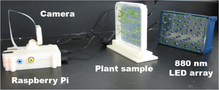
Setup of imaging station. [back to top](#contents)1. If you are going to backlight your plants (if they are growing on tissue culture plates or in solo cups) place the plants between your Pi imaging system (at the proper distance from the lens so that the plants/seedlings are in focus) and the LED array.
Note: If you are using plants in plates, you can use a plate holder to keep the plates vertical. 3D print instructions [here](http://www.thingiverse.com/thing:418614).2. If you are going to do any time lapse, secure the camera and plants/plates with tape to minimize vibration issues during imaging.
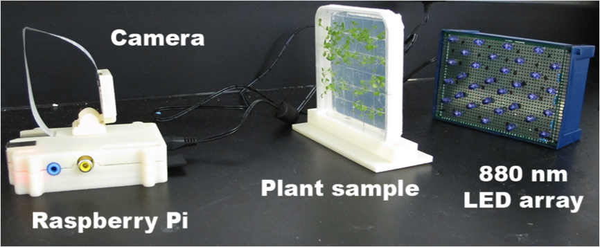
Figure 7. Backlight imaging set up.
Liquid sterilization. [back to top](#contents)
1. Aliquot desired amount of seeds (typically 18-100) into labeled 1.5 mL tubes.
2. 500 uL of 50% bleach/0.02% Triton X-100 to each tube.
3. Rotate tubes on a tube rotator or by hand for exactly 5 minutes.
4. Spin down at ~1000x g & pipet off all liquid using a 1 mL tip with a 10uL tip added on the end.
5. Add 1mL of Sterile H2O and rotate or flick the tube to rinse seeds of bleach.
6. Repeat steps 4 & 5 at least 3 more times or until bleach smell dissipates.
7. In the hood, plate the seeds the appropriate media plates, i.e. 1/2 X MS media.
8. Seal all plates with 3M surgical tape.
9. Wrap stacks of plates in aluminum foil and place at 4°C for approximately 2 days to stratify the seeds.
10. Transfer to a controlled environment chamber.
Measuring Hypocotyl Length. [back to top](#contents)1. Transfer files from Raspberry Pi to a folder that will contain only the images to be analyzed (e.g. 72-96 hours worth of images)
Note: If Fiji is not downloaded onto your computer, do so now by going [here](http://fiji.sc/Fiji).2. Using Fiji, go to file > Import > Image sequence and select the folder of images that you would like to analyze.
3. Go to Analyze > Set Scale. Use ruler in image to set the measurement scale to mm.
4. Go to Analyze > Set Measurements. Chose Bounding Rectangle, Stack Position, Invert Y coordinates.
5. Use Straight tool, select segmented line.
6. Left Click on Root/Hypocotyl junction, then click line that lies in the center of the hypocotyl ending with a right click at hypocotyl/Cotyledon junction. You should have a line accurately measures hypocotyl.
7. Go to Analyze > Measure (Use Command M).
8. Advance to next image, repeat 7 and 8 on the same seedling until all images are analyzed.
9. Save Data to spreadsheet.
10. Go to Analyze > Clear results.
11. Repeat 7-11 on new seedling.
12. Do for all quality seedlings. If the seedling does not begin growing by 24 hours or if is planted directly next to another seed, then the measurements for that seedling/s should not be taken.
13. Each measurement will need to be assigned a time of capture.
14. Plot Length vs time.

Figure 8. Example of Arabidopsis thaliana hypocotyl being measured.
Recent Blog Posts
-
 Posted on 02 Feb 2018
-
 Posted on 09 Jan 2018
-
 Posted on 05 Jan 2018
-
 Posted on 17 Sep 2016